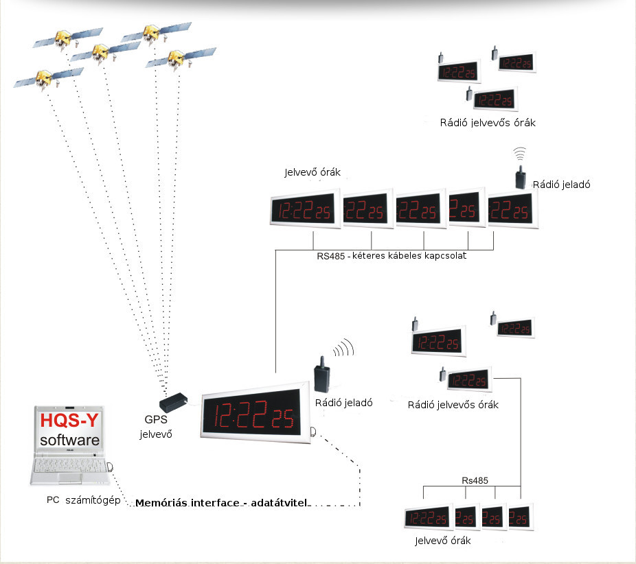
Digital clocks are widely used these days. The HQS-Y digital clock system is used primarily in schools and other facilities. In addition to measuring time, the clock can also be used to control the school bell. The network consists of master and an unlimited number of slave clocks.
The master clock of the network is called HQS-Y01, while the slave clocks are signified by numbers and letters based on the number of clocks (e.g. HQS-Y02, HQS-Y03, etc.) The numbers indicate the number of slave clocks within the system.
The clocks are connected to the system wirelessly (radio) or via wired (RS485) connections where both connections can be used. The master clock receives the exact time via the GPS receiver and then synchronizes with the other clocks. The clocks can also be controlled by computer, transmitting the information to the master unit, which collects and stores the data in the EEPROM memory until the data is modified. Each clock has an integrated sensor which registers outdoor light conditions and adjusts its display brightness accordingly.
Location, mounting:
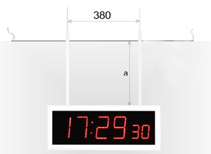
The HQS-Y... digital clocks can be mounted on the wall or on the ceiling:
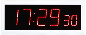 |  |
| Wall-mounted clocks using hooks and screws
| Wall-mounted clocks using metal rods |
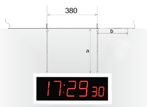 |  |
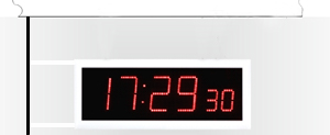
| Clocks mounted on ceiling using chains
| Clocks mounted on ceiling using metal rods. Can be easily mounted on and affixed to a suspended ceiling. |
Connecting the clock
The computer system has an interior master clock which is in synch with all external sources: that is to ensure that all clocks tell the exact time. Most often the GPS receiver is used for this purpose. Note that the new HQS-Y... V3.2 (version 3.2) clocks can operate as a master clock, exclusively as a receiver or as a transceiver, as well.
The HQS-Y... clocks are automatically given the master clock function through the connected HQS-GPS V3 GPS receiver, which means that any clock can be a master.
In the case of frequency-controlled clocks, they must be placed in the middle of the building in order to use their range as efficiently as possible. In the RS-485 wired system the master clock should be starting node of the network.
2. TRANSCEIVER CLOCK
The clocks in the HQS-Y… radio network system gain a transceiver (repeater) function by placing a small HQSJ01 module into the GPS receiver port (MOD6 phone port). This is only an option for systems that are equipped with a radio connection. The clock that operates as a repeater reads the synchronized signal, then transmits it to those clocks that are in the vicinity but still unsynchronized. By using several repeaters, the network of clock systems may be increased indefinitely.
In those systems with RS-485 connection the repeater does not really play any role, as the range of the clocks can be up to 1000 m.
3. RECEIVER CLOCK
All HQS-Y… clocks operate as a receiver, since that’s what they were originally designed to be: by leaving the above-mentioned MOD6 phone port empty, the clock will automatically work as a receiver clock.
4. In the RS-485 network system all clocks are connected to the two-wire cable of the suitable port. This means that the cable denoted as “A” must be connected with the port “A”, and the same is true for “B”, as well.
The power supply can be either master or stand-alone.
In the case of the master power supply, the “+” pole must be connected to the “+” port, while the “-” goes with the “-”.
Implementation:
Once the clock has been connected, its implementation is quite easy, just connect the clock to the power supply, and it will then operate with its predefined functions.
Systems with radio connection (2.4GHz or 433MHz) are implemented without repeater function. In such cases, if the clock or clocks fail to tell the exact time after synchronization, select another clock that runs properly and has a suitable connection with the others, and then set it up as a transceiver clock using the HQS-J01 module. Synchronization may pose a problem due to the characteristics or construction of the objects. There may be more repeaters in a single system, but do not increase their number needlessly, use only as many as necessary. The rational distribution and of the master clock and repeater enables the safe use of the clock system with one or more objects – basically, there is no limit. However, be aware that the distance between two clocks cannot be greater than the range of action, which is 1000 m in optimal circumstances, although, with objects that are mounted on a wall, it is no more than 100 m.
Method of operation:
When the clock is turned on, first several figures of 8 appear, as a test. Following this:
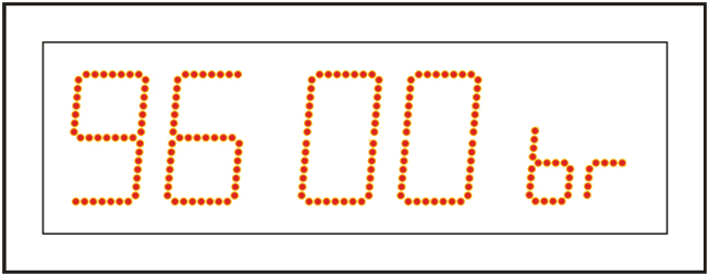
1. If the clock functions as a master clock with a GPS port (receiver), it will first recognize the speed of communication of the GPS port (receiver) and briefly display a number (“9600” or “4800”) referring to the speed of communication (bit/sec).
Following this, the clock displays “GPS on”, indicating that the GPS receiver is now successfully connected and the clock is now awaiting the precise time from the GPS receiver.
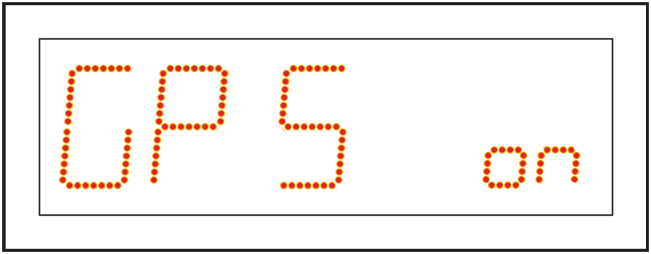
Under normal circumstances, at first initiation, the clock will need 3-5 minutes to display the exact time, though later this time period will be significantly reduced to 1 minute, so for each subsequent start the clock will display the exact time within 1 minute.
2. When the clock functions as a slave (receiver) or transceiver (repeater) clock, we first see figures of 8 for a few seconds upon start, as a test. Then the display reads “rAd on”, which means that this is a receiver clock and it is currently waiting for the synchronization data from the master clock.
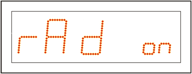
The master clock transmits the time every 10 seconds (or every 1 minute). As soon as the clock receives the update for the exact time, it will display it.
3. The clock may also operate as a completely stand-alone device, in this case the setup must be done manually. This method is generally not recommended as it could happen that the clock fails to tell the exact time. Another possibility is that upon the explicit request of the customer, a module is installed which, in case of power supply failure, ensures that the exact time is set and displayed again once the power supply is reinstalled.
If the clocks works with a GPS receiver or is connected to the network to synchronize the time, the exact time is automatically corrected. For clocks that are not equipped with a GPS receiver, the exact time must be set manually.
Guarantee, service:
There is a two-year warranty, which means that we can guarantee our customers the seamless operation of the devices for two years.
The warranty does not cover devices damaged by natural disasters, or in acts of vandalism, or when the devices were incorrectly opened, i.e. not by an expert.
Spare parts and professional servicing are ensured.
Maintenance:
The devices do not require any special kind of maintenance, only regular cleaning and dusting off for the screen.
Technical specification:
Further options:
The device is constructed so that there is room for further options.
Potential errors:


